Tweeter
For details about the Electrostatic devices see the links on the left.
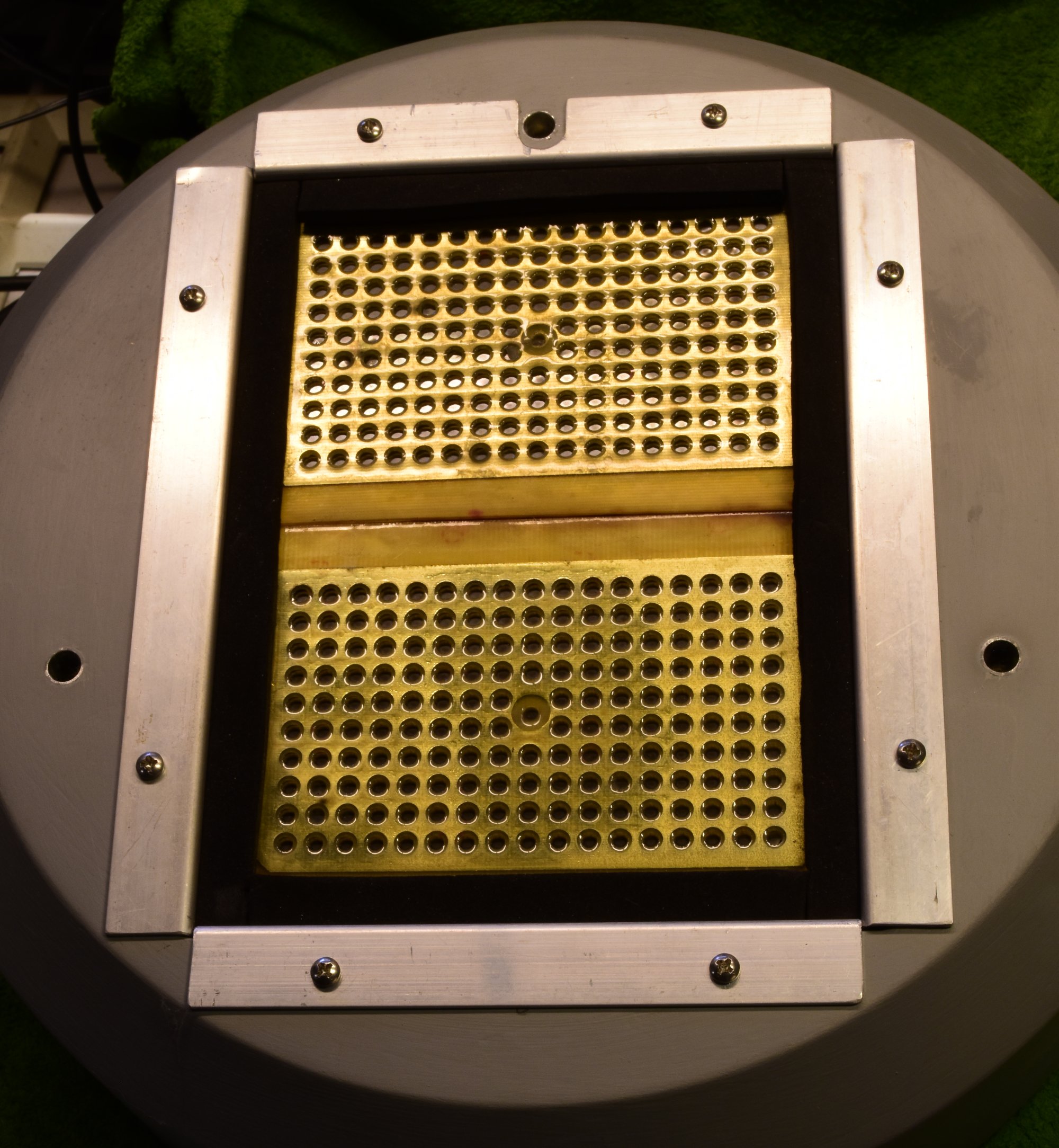
The Tweeter unit seen from the bottom side.
The ESL modules are kept in place by 'J' shaped aluminium profiles and foam strips with glue on one side. (the type you can buy as weather-strip)
Note the three holes for the pillars. A short piece of 8 mm aluminium tube has been glued in the holes. The studs are made of 8 mm alu-tube, which define the height of the tweeter above the midrange unit, and a 2 cm longer 6 mm diameter tube which fits in these holes. The two studs in the front carry the cables for mains voltage and tweeter signal.
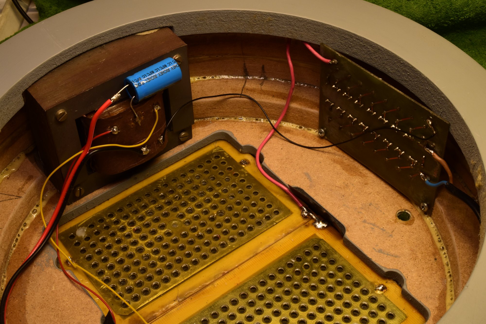
Inside the Tweeter compartment.
For the photo the rockwool damping material has been removed.
It can be seen that the housing is built from a number of ring-shaped plates of MDF, glued together.
Left the step-up transformer, right the High Voltage PCB. Normally both are covered with an insulating foil.
Note the insulation strips near the connections, and the extra free space where the electrical connections to the ESL modules are made. We deal here with voltages far over 5 kV, and we should not regard MDF as a good insulator at these voltages.
Note the electrolytic capacitor 1000u/63V near the transformer. It blocks possible DC from the amplifier. The DC resistance of the transformer's primary is only 70 milli-Ohm, so the slightest offset voltage will create currents of Amperes. It should once be replaced by a non-polarized type, although the signal voltage across the capacitor is only a few hundred milliVolts (XC @ 1 kHz = 0.16 Ohm-cap).

The High Voltage Board.
Produces around 5000 Volts for the membrane of the ESL.
Note that these capacitors are rated 250 V. To my opinion that should be 500 V at least.
The diodes are 1N4007, which can withstand 1000 Volt.