TestTool FLT
The TestTool_FLT can be used to solo test the Filter boards FLT or the complete Box electronics.
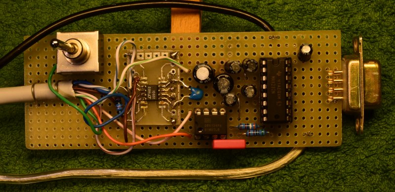
The CAT-5 cable has a RJ45 connector on the other end and goes to the FLT-board.
The black cable has an RCA connector to e.g. an audio signal generator.
The metallic cable has a USB-A connector and is only used to supply the board.
The DB9 connector goes to a PC where the program TestTool_FLT should be running. Be sure to select the proper serial port. This may be the standard serial port (COM1 on a windows machine) but a USB-serial converter will also work.
The FLT under test should have it's 12 Volt supply.
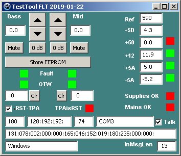
Screenshot of the TestTool_FLT program on WXP.
Top left we see up/down buttons for the bass and mid-range volume setting, relative to the tweeter. Settings are saved on exit.
Below that are butons 0dB to force it to 0 dB, and buttons Mute to set the channel to minimal gain.
The button Store EEPROM command to store the Bass and Midrange settings in EEPROM on the FLT board.
The fields Fault, and OTW indicate the error status of the Power amplifiers for Bass and Midrange. OTW= Over Temperaturee Warning.
The fields ClipsB and ClipsMT show the values of the ClipCounters.
ResetTPA brings the power amplifiers in reset mode. (Start-up value for this tool)
Fields relating to the Power Amplifiers are only relevant when the TPA boards are connected to the FLT.
Top right we see the ADC value of the 2.5 Volt reference voltage, and the +5Digital voltage derived from this reference.
Below that we see the measured supply voltages. The green fields willl turn red when out of range. This range check is done locally in the test tool.
SuppliesOK reflect the range check status in the FLT.
Mains Fail indicates that no mains zero crossings were seen. Only relevant if the Power board is connected to the FLT.
Fields at the bottom show increasing numbering and content of the outgoing and incoming messages. It provides diagnostic informaton.
The bottom line shows the operating system on which the program runs.
The serial port name must be filled in once. It is saved on exit of the program.
The checkbox Talk starts communication with the FLT unit under test. A wrong serial port name may cause the program to crash.
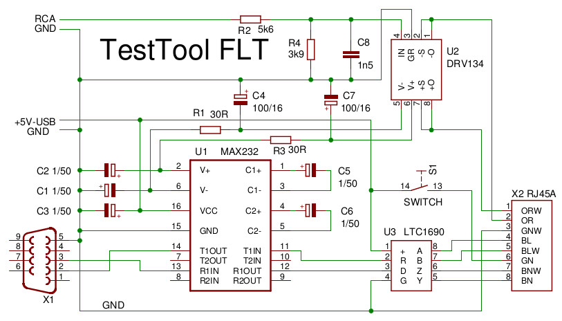
Schema of the TestTool. U1 converts between RS232 and 5Volt logic voltage, and U3 converts between 5Volt logic voltage and RS422 levels.
U2 converts the RCA signal to symmetric. A first-order filter R2,4, C8 limits the input bandwidth to approximately 40 kHz.
U2 is supplied by the positive and negative voltages generated by U1.
S1 switches the +5 Volt to enable the main power if we are testing the complete box electronics.
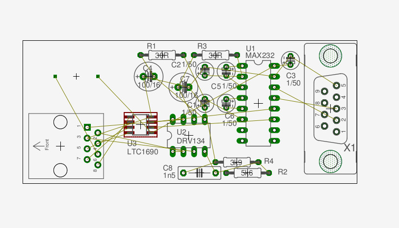
The board has not been routed as a real PCB. This layout is just a guide to handwiring it.