Power board
The Power Board switches mains power to the PSU and provides an indication signal MAINSOK.
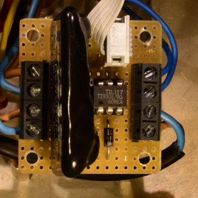
For this board no real PCB has been designed, the Eagle board file has been routed but that is used only for hand-wiring the board.
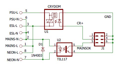
Schema
The operation is quite self explaining.
The solid-state switch D2W202F switches only on mains voltage zero crossings which helps limiting the rush-in current.
The neon indicator should have a built-in series resistor. 220 kOhm is usual for 230 VAC.
The optocoupler should work well with 1 mA input current. The arduino input on the FLT board has an internal pull-up of some 10's of kOhms, so you wo'nt even need a very high CTR type.
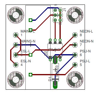
Layout
If one ever should make this to a real PCB use much wider traces so it might survive an accidental short circuit in the mains circuit.